The Jabal Hafit anticline
Geology, Aerial Photogrammetry
This case study has been kindly shared to us by Reuben J. Hansman and Uwe Ring of the Department of Geological Sciences, Stockholm University. This survey has been published in the Geological Society of America journal Geosphere (Hansman & Ring, 2019).

Click here to access the abstract and the complete PDF paper.
Acquired area and survey goals
Back in November 2017, in the United Arab Emirates, the Jabal Hafit anticline (a folded mountain) was selected as the subject for 3D reconstruction mapping. This is because of the anticlines characteristics, which includes excellent geological exposure and a rugged terrain. These features make it an ideal scenario for testing a method based on unmanned aerial vehicle/remotely piloted aircraft (UAV/RPA) photos that were then processed by photogrammetric software, such as 3DF Zephyr. More specifically, the goal here is to present a workflow for field geologists that includes the following steps:
– acquisition of RPA images of geological outcrops;
– photogrammetric 3D reconstruction using 3DF Zephyr Aerial;
– extraction of geological information from the 3D reconstruction to create a 3D geological model
Data collection and tools
For the first step of the survey, a DJI Phantom 4 quadcopter was used to cover an area of 3.32 km2, that cut a transect across the anticline.
The drone was paired with a wide-angle camera having a focal length of 3.6 mm (35 mm camera equivalent: 20 mm) and a 1/2.3-inch (6.17 mm × 4.55 mm) complementary metal-oxide-semiconductor (CMOS) sensor.
Two different apps remotely controlled the flight: the first one was for manual flight around cliff faces with the camera tilted toward the horizon to maintain a perpendicular view of the rock surface, while the other app was autonomous and used on areas with flatter terrain with the camera pointing down vertically.
The data was collected in nine days and over 40 flights, for a total of 5728 images and 9 and half hours of flight time, setting the above ground level (AGL) flight height between 50 and 80 meters and a ground sample distance (GSD) of 2.2 cm/pixel to 3.5 cm/pixel. The overlap between the photos was between 60% and 96%.
Moreover, thirteen markers were placed on the ground throughout the mapping area, and their GNSS coordinates were measured with a Trimble GeoExplorer 6000 Series device. The estimated horizontal accuracy of the GCPs in the field, with uncorrected (autonomous) GNSS, was 3.2–6.9 m, RMS (root mean square) 63% confidence. This was considered acceptable due to the size of the mapping area (i.e., 4.0 km × 0.8 km). Unfortunately, no satellite-based augmentation system (SBAS) was available, and no post-processing corrections of the GNSS measurements was carried out. This could have achieved sub-meter accuracy.
These markers were then used as ground control points (GCP) to geo-reference the model and improve its own accuracy. The Coordinate Reference Systems were WGS84 and EGM96 for the horizontal and vertical datum respectively.
Data processing
The 3D reconstruction process started by importing the images into 3DF Zephyr Aerial Education (ver.3.503). Given the huge dataset, the project was split into four areas to generate a sparse point cloud in each subproject.
Data processing was performed on two cloud computers with the following specifications:
Paperspace:
⦁ Processor: Intel Xeon E5-2623 v4 @ 2.60 GHz, (8 vCPUs), Maximum ~3.20 GHz
⦁ System RAM: 30 GB
⦁ GPU: NVIDIA Quadro P5000 Pascal 2560
⦁ CUDA Cores 16 GB
Amazon Web Services:
⦁ Processor: Intel Xeon E5-2686 v4 @ 2.60 GHz, (16 vCPUs), Maximum ~2.30 GHz
⦁ System RAM: 122 GB
⦁ GPU: NVIDIA Tesla M60 Maxwell 2048
⦁ CUDA Cores 8 GB
Once the subprojects were merged into a single one, the GCPs were used to run a bundle adjustment and improve the overall accuracy of the 3D reconstruction.
Extraction of Geological Information and final results
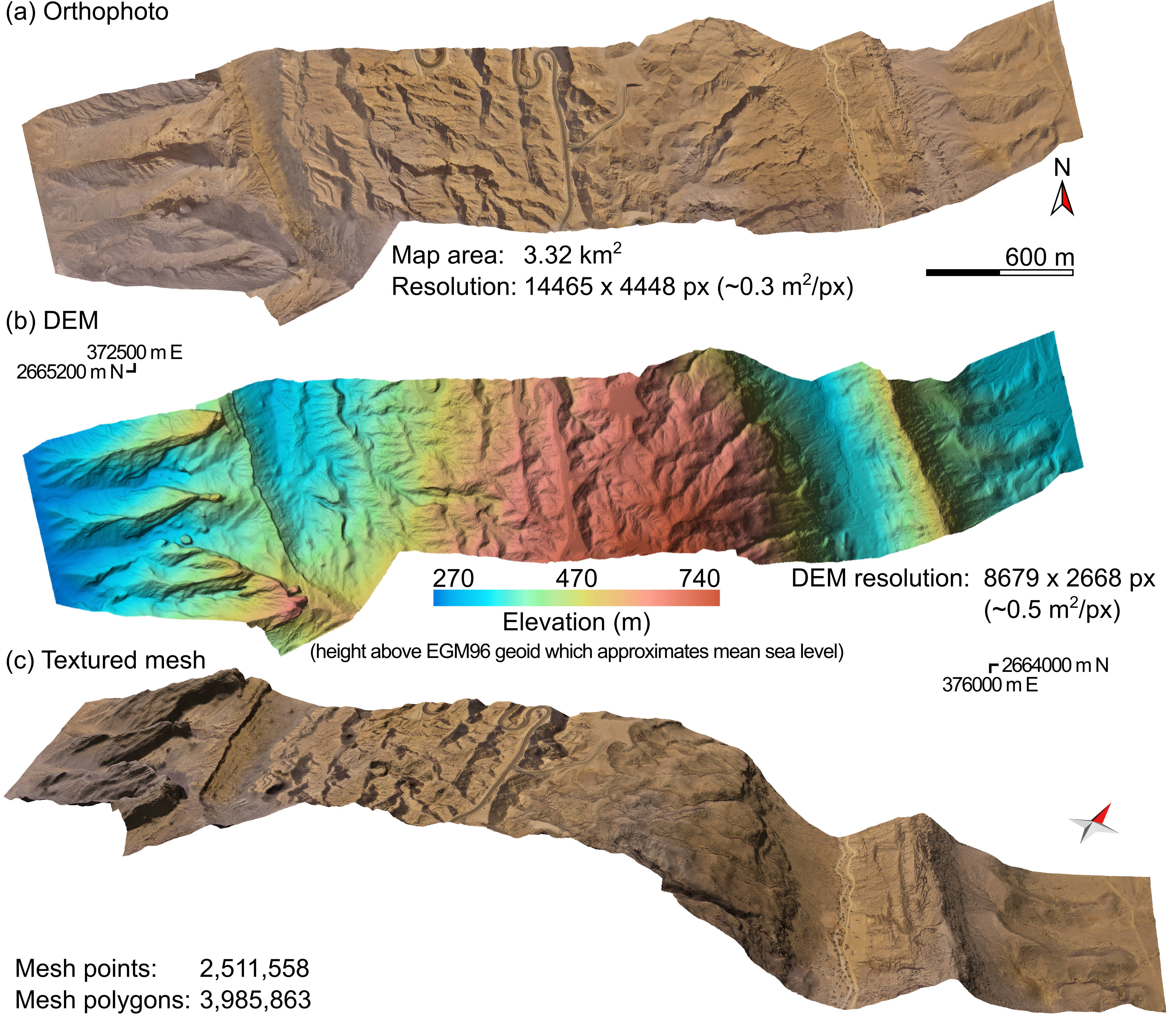
The 3D reconstruction led to a dense point cloud made up of 2,605,021 points and a mesh with 3,985,863 polygons. Other outputs include an orthophoto, a high-resolution DEM, and a textured mesh (Fig. 1).
The computation time of each reconstruction phase is available in the complete PDF paper linked above.
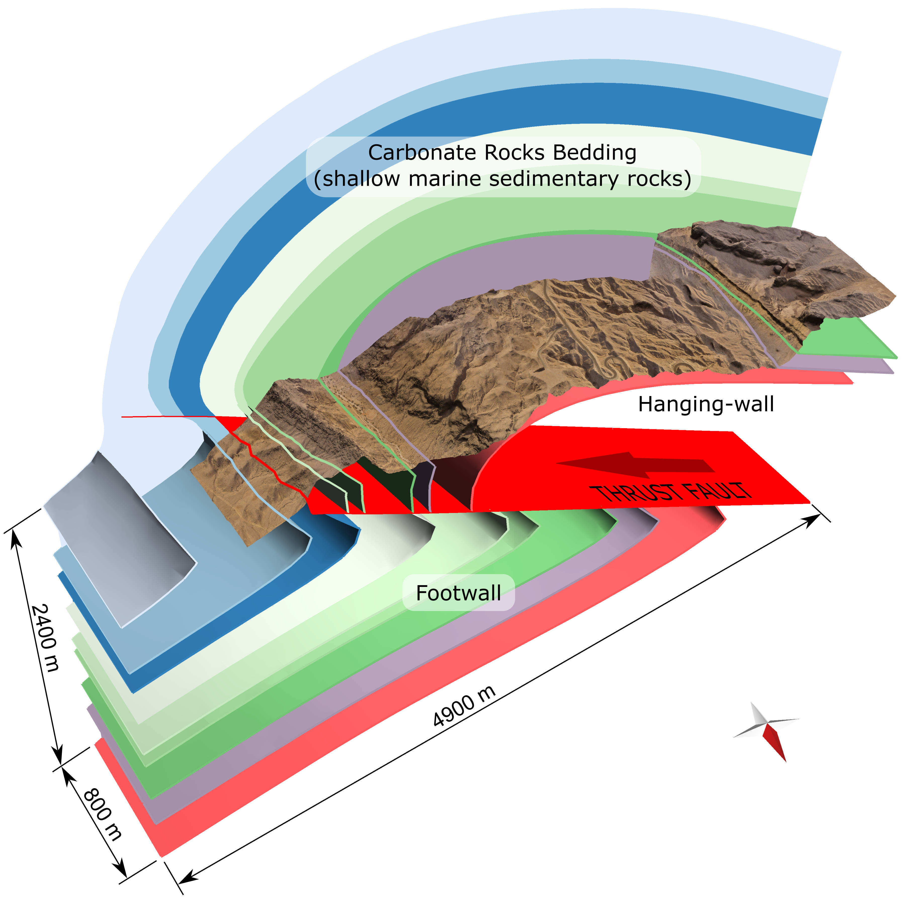
Besides the 3D reconstruction process, third-party applications were used to measure orientation data of geological structures from the generated output. This includes Maptek PointStudio and Move TM from Petroleum Experts Ltd. The first software was used for measuring the orientation of bedding, lithological contacts, and faults. These measurements were then used to create a 3D model of the subsurface geology. The second software was used to create a true 3D geological terrain model by combining the textured mesh generated by 3DF Zephyr Aerial with the geological data previously extracted from the point cloud (Fig. 2).

Figure 1. Outputs from 3DF Zephyr Aerial of a transect across the Jabal Hafit anticline. (a) Orthophoto, (b) digital elevation model using coordinate system UTM, Zone 40 North, and (c) textured mesh. Red arrow indicates north direction, modified from Hansman & Ring (2019).

Figure 2. Textured mesh output from 3DF Zephyr Aerial, with geological interpretation of the sedimentary rocks and fault based on orientation data derived from the mesh/point cloud. Red arrow indicates north direction, modified from Hansman & Ring (2019).
This case showed the benefits of aerial-photogrammetric 3D reconstructions. This solves many field-related issues, such as the possibility to cover every portion of the mapping area with a RPA. This is useful especially when dealing with difficult areas to reach by foot. Also multiple analyses of the 3D reconstruction can be carried out, without the need of additional fieldwork.
It’s important to note that a new test of this dataset has been done after two years with an updated 3DF Zephyr Aerial version (n. 4.504). The same settings and GCPs of the first workflow were used for the SfM phase along with a further Bundle Adjustment.
The final mean residual significantly changed, decreasing from a previous error of about 15m to 2m, thus showing a great improvement in terms of accuracy.
| GCP | 3DF Zephyr Aerial ver. 3.503 Residual (m) | 3DF Zephyr Aerial ver. 4.504 |
| GCP01 | 4.4 | 0.065 |
| GCP02 (Control) | 4.0 | 0.418 |
| GCP03 | 5.5 | 0.113 |
| GCP04 | 8.0 | 0.113 |
| GCP05 | 5.8 | 0.436 |
| GCP06 (Control) | 4.3 | 7.163 |
| GCP07 | 5.5 | 0.138 |
| GCP08 | 1.8 | 0.086 |
| GCP09 (Control) | 2.9 | 3.222 |
| GCP010 | 1.9 | 0.084 |
| GCP011 (Control) | 2.0 | 17.299 |
| GCP012 | 4.8 | 0.013 |
| GCP013 | 3.4 | 0.042 |
References
Hansman, R. J., & Ring, U. (2019). Workflow: from photo-based 3D reconstruction of remotely
piloted aircraft images to a 3D geological model. Geosphere, 15.
https://doi.org/10.1130/GES02031.1


