Quarry volume monitoring
All the data in this case study was collected by the Zerolab design studio and has been kindly provided by Diego Curri and Simone Malusardi.

Context analysis and survey goals
Located in the northern part of Milan, the quarry has an area of about 106,000 square meters and has an active area of about 52,000 square meters. Nowadays the quarry is being exploited as landfill for aggregates.
Every two months the quarry needs to be monitored to measure how many cubic meters of material has been added.
The aim of these measurements is to periodically survey the volume increase of quarry material.
Up until May 2019, GPS topographic instrumentation was used for surveying the land, however, as of June 2019, this has been paired with a photogrammetric survey processed in 3DF Zephyr.
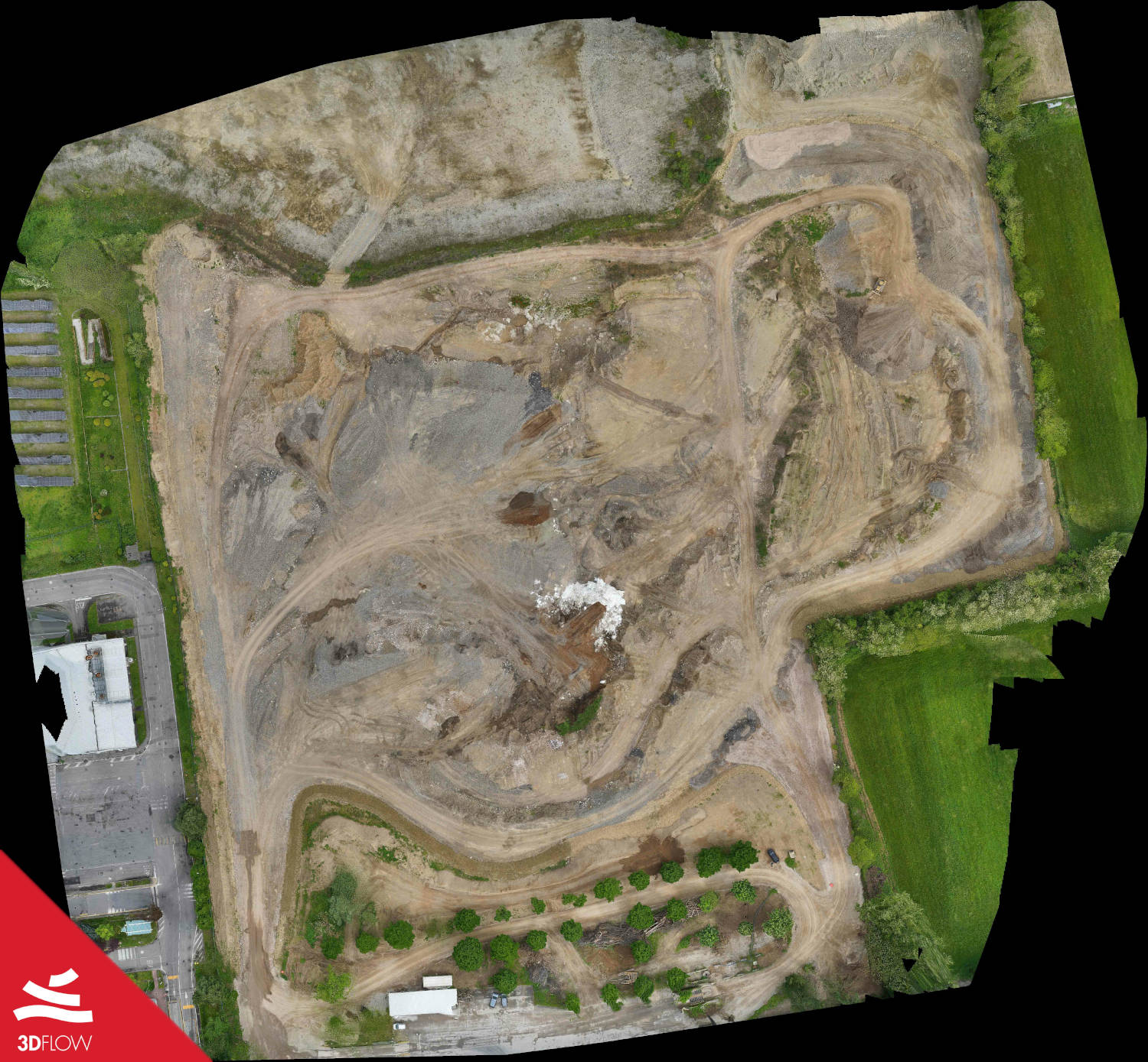
True orthophoto describing the whole area of the quarry. GSD: 5cm/pixel
Photogrammetric surveying equipment
The photographic data was collected using a UAV specified for critical operations according to ENAC (Italian Civil Aviation Authority). This particular UAV was a DJI Matrice 600 hexacopter (with triple redundant controller), along with a 42.6 megapixel Sony Full-frame a7R III mirrorless camera (paired with a 24mm Carl Zeiss prime lens).
Surveying equipment
To georeference the model, 21 targets were placed across the entire quarry area at different elevations to better distribute the error value across the 3D model. These targets have been implemented using a spray can on the ground which speeds up the next surveying steps.
The targets were measured with a GPS Trimble R8s GNSS device, (supported satellite navigation system: GPS and Glonass). Planimetric positioning accuracy is 8 mm + 0.5 ppm, while altimetric accuracy is 15 mm + 0.5 ppm.
Mission planning and Capture details
Two flights were planned to capture the quarry (using the UAV and full frame camera): the first was performed at a flight height of 45 meters with the camera oriented in nadiral position, while the forward overlap and side overlap of the images were 85% and 80% respectively. During the first flight (≈13 minutes) 573 images were captured with a 0.9 cm/pixel GSD.
The second flight was transverse to the first, and was captured at a height of 40 meters, tilting the camera 65 degrees to better define quarry elevation differences. Furthermore, during the second flight (about 10 minutes) the forward overlap threshold is 80% whereas the side overlap is 76%. 434 images were captured with a ground sample distance of 0.8 cm/pixel.
The camera was set up to capture one photograph per second, M settings are provided below:
⦁ ISO 200
⦁ shutter speed 1/1000
⦁ auto aperture.
The camera focus was set to automatic using 399 points of focus across the frame.
Data processing
The images have been processed using 3DF Zephyr 4.5 (Aerial version) on a computer with the following specifications:
– Processor: Intel Core i9-7920X @ 2.90 GHz
– 128 GB RAM
– Samsung SSD 970 500GB NVMe
– Graphics cards: 2x Nvidia GTX 1050 TI and 1x Nvidia GTX 1080
The preset category Aerial/Default was used for the orientation, densification and 3D reconstruction. The project took 7 hours and 35 minutes to fully process in Zephyr.
The first phase oriented the entire dataset (1007 images) producing a sparse point cloud made up of about 390,000 points. Before proceeding with the other steps, 21 control points were placed by defining their 2D positions on images. A text file including the 3D coordinates of the GCPs was imported – Coordinate Reference System: wgs84 UTM 32N – so the sparse cloud has been scaled and georeferenced by setting the Bundle Adjustment threshold to 80% as well.
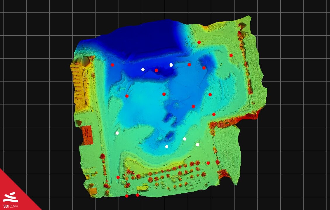
GCPs positioning in 3DF Zephyr Aerial – Constraints (red points) and controls (white points)
In 3DF Zephyr, GCPs were defined as follows: 15 constraints and 6 controls.
The final mean residual, as well as the residuals of each GCP, can be found in the chart below.
Final Mean Residual on the controls: 0.0287889 meters
| GCP | RESIDUAL | X RESIDUAL | Y RESIDUAL | Z RESIDUAL |
| M07 | 0.0145952 | -0.00354165 | 0.00968354 | 0.0103298 |
| M10 | 0.0103298 | -0.000651151 | 0.0155713 | 0.00795587 |
| M21 | 0.0856706 | -0.0103391 | 0.0222217 | 0.0820899 |
| M09 (control) | 0.0203557 | -0.000452431 | 0.00869861 | -0.0183979 |
| M16 (control) | 0.0326558 | -0.00429861 | 0.015961 | 0.0281633 |
| M18 (control) | 0.0162642 | -0.0016248 | 0.00534493 | -0.0152747 |
| M20 (control) | 0.0112154 | -0.00768674 | 0.0052125 | 0.00628715 |
| M23 | 0.0348789 | -0.0180623 | 0.00676341 | -0.0290611 |
| M24 (control) | 0.0106481 | -0.00904248 | 0.00357196 | -0.00434245 |
| P1 | 0.041712 | 0.0172642 | -0.0276393 | -0.0260366 |
| P2 | 0.0307481 | 0.0296586 | 0.00528889 | -0.00615135 |
| M11 | 0.0380081 | -0.00518436 | -0.00108522 | 0.0376372 |
| M01 | 0.0383413 | 0.0142226 | -0.0150055 | 0.0322894 |
| M22 (control) | 0.081594 | -0.0221433 | 0.0257209 | 0.0742003 |
| M14 | 0.0196666 | 0.000129032 | -0.0162646 | -0.0110554 |
| M15 | 0.00553043 | -0.00478175 | -0.000123837 | -0.00277584 |
| M17 | 0.0115225 | 0.005335 | -0.0039444 | -0.00942065 |
| M02 | 0.00470059 | 0.00428093 | -0.000317292 | -0.00191532 |
| M12 | 0.0189772 | -0.00333276 | -0.00379005 | -0.0182938 |
| M03 | 0.0557805 | -0.0189463 | 0.000847694 | -0.0524575 |
| M19 | 0.0164279 | -0.00605108 | 0.00779365 | -0.0131347 |
The extraction of the dense point cloud has generated about 11 million points, while the mesh extraction produced about 20 million polygons. The texture has been created with a size of 8192 pixels.
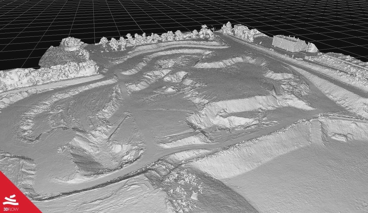
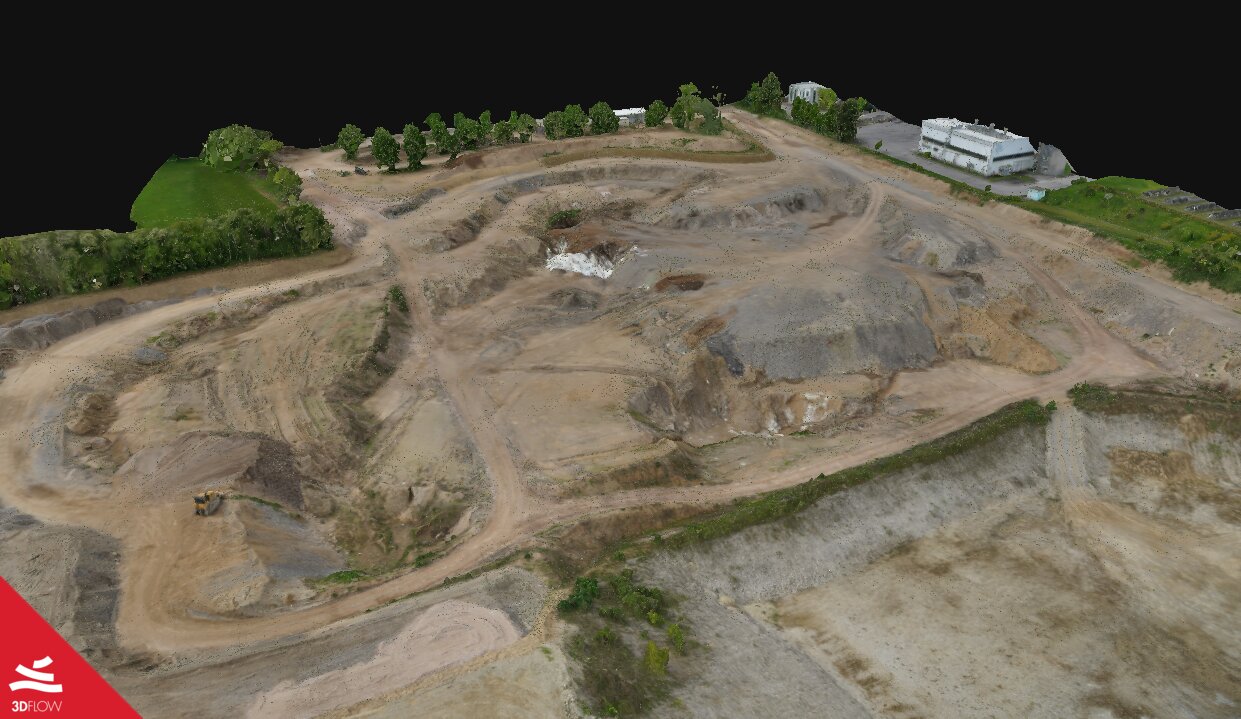
3D mesh geometry (left) and texture (right)
The same aerial acquisition procedure and 3DF Zephyr settings have also been used for the two subsequent 3D models of the quarry. Afterwards, the volumes of the three models (Projection Volume filter) were calculated inside the software in order to monitor the volume increase of the amount of material.
Below you can see the additional outputs generated by 3DF Zephyr:
– true orthophoto (compressed data)
– digital surface model (DSM)
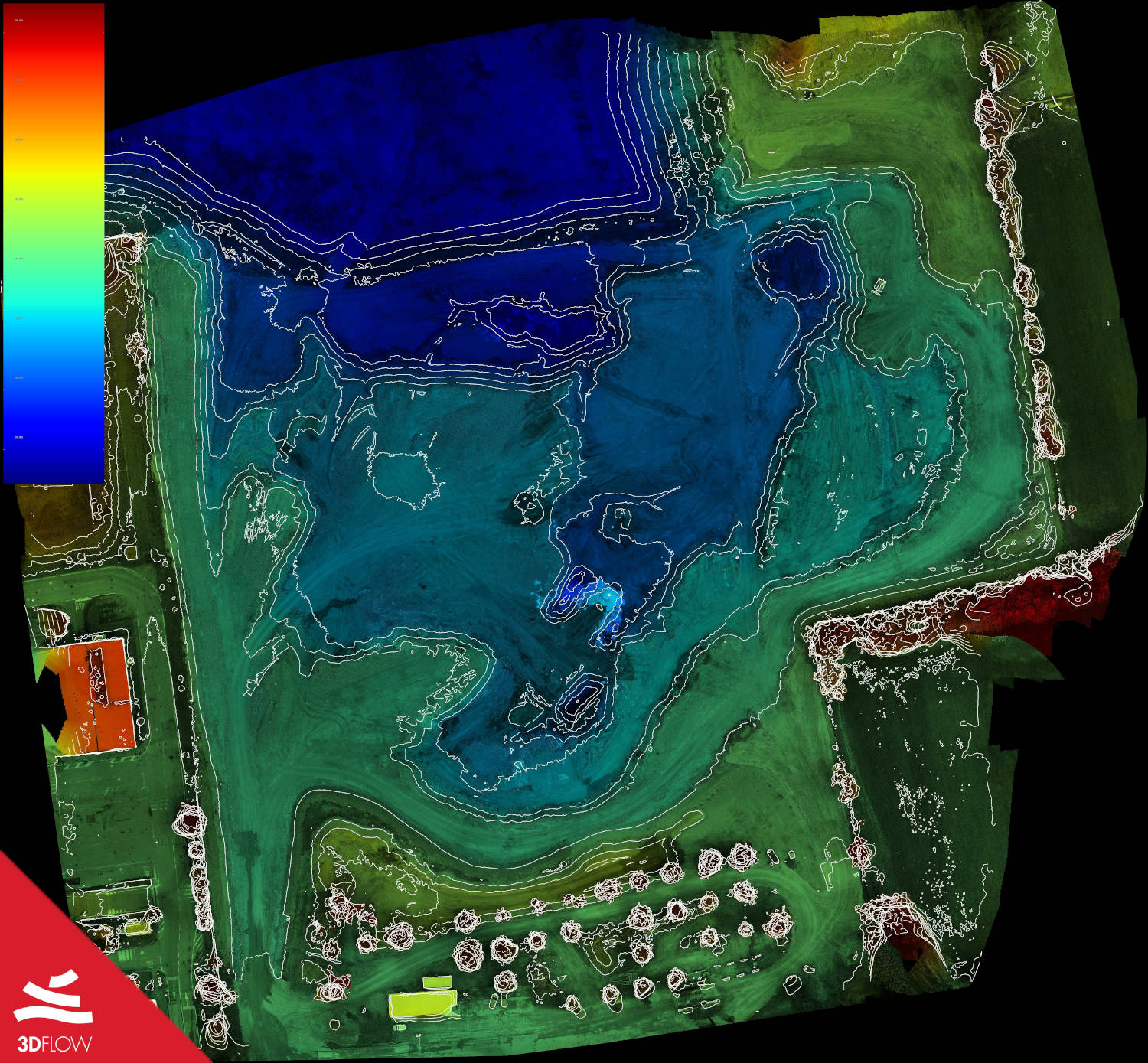
– contour lines generated on the 3D model and projected on the DSM

