Tutorial #A10 : Camera Optimization
Understanding camera optimization
Welcome to the 3DF Zephyr tutorial series.
In this recipe, you’ll learn camera optimization (also called “bundle adjustment”) and how/when to use it.
Launching an additional bundle adjustment is available only in the 3DF Zephyr full-featured version since it’s required to pinpoint control points (2D or 3D constraints) before running the optimization process.
What does “camera optimization” mean?
The camera optimization process improves the initial camera orientation result by the Structure from Motion phase, especially when dealing with low-quality imagery.
The algorithm behind the camera optimization, the Bundle Adjustment, is a non-linear minimization procedure that adjusts points and cameras by minimizing the reprojection error of points. In 3DF Zephyr, it’s performed at the end of each merge, and a final bundle adjustment with all points and cameras is always performed at the end of the Structure from Motion phase.
The full-featured version of 3DF Zephyr allows users to manually run additional bundle adjustment steps by adding 2D or 3D constraints.
Since the bundle adjustment works on the internal and external camera parameters, keep in mind that only the sparse point cloud will be affected by the bundle adjustment. Any existing elements, such as already-generated dense clouds or meshes, will be deleted once the camera optimization is complete. That is why running the camera optimization after the sparse point cloud generation, and before moving to dense point cloud generation, is highly recommended.
Zephyr offers an easy-to-use slider to control the camera optimization process, in which you can define how you are confident in the 2D/3D constraints you have added to the Zephyr project. It’s worth noting that the more confidence you set in the manual constraint, the less confidence Zephyr will have in its tie points. This means that if you set the confidence to 99%, the accuracy of the constraints will be very high, but at the expense of accuracy in areas of the 3D model not affected by 2D/3D constraints.
How camera optimization works
In 3DF Zephyr, camera optimization can be performed using either control points or ground control points (standard control points with coordinates collected onsite via GNSS devices or total stations) as constraints for bundle adjustment.
By using control points, the bundle adjustment will focus only on the XY positions (2D constraints) of the points to reduce their reprojection error.
By using ground control points, the bundle adjustment will also involve the coordinates associated with the GCPs (3D constraints), which the user has previously imported. Please note that control distances can also be used as 3D constraints. That is valid for cameras’ GPS coordinates, too (better if RTK/PPK).
As for 2D constraints, in the “Tools” menu (1) select “Workspace” (2) and then “Optimize cameras parameters” (3).
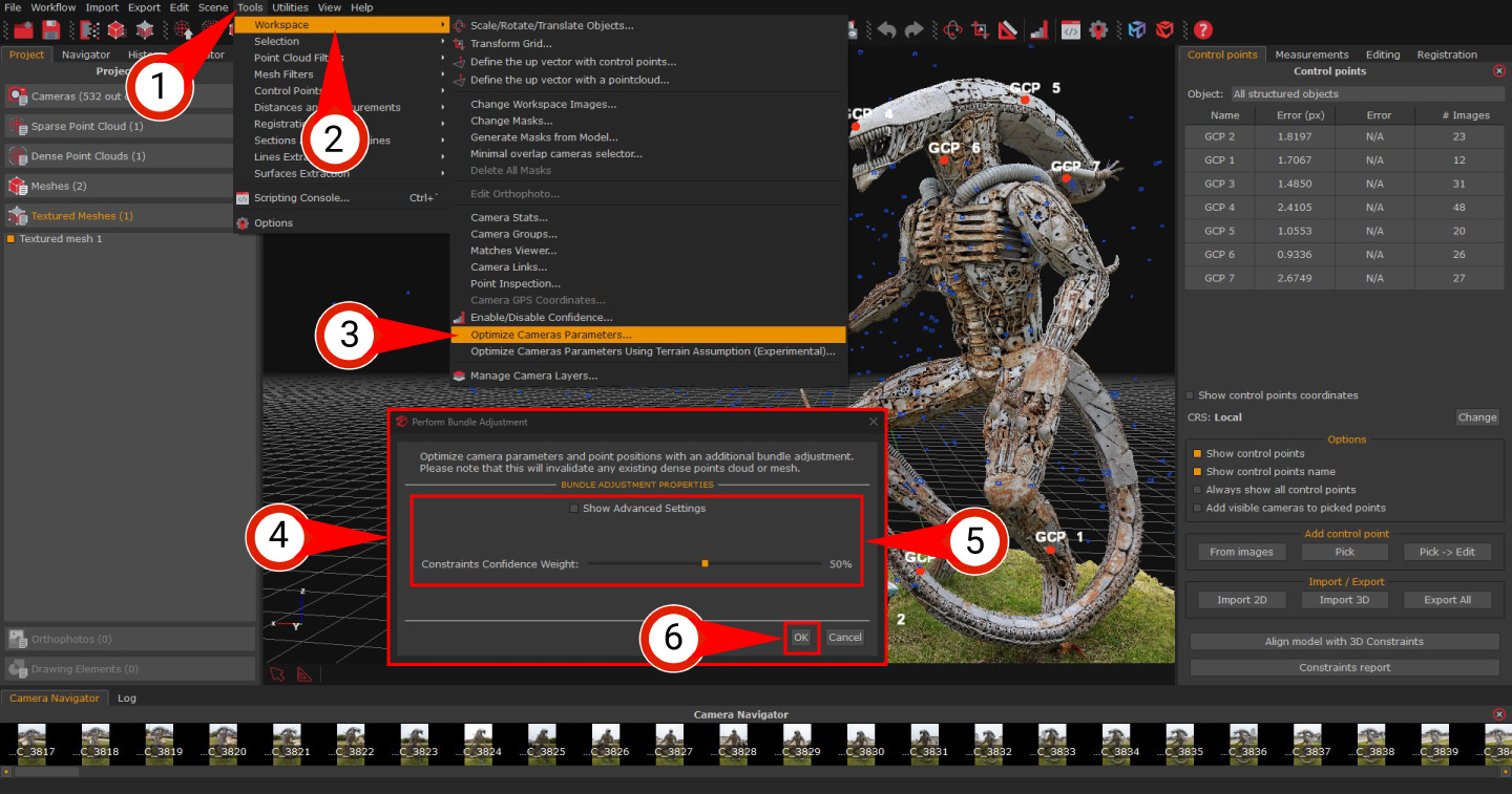
The “Perform Bundle Adjustment” (4) window will appear.
Zephyr allows you to set “Constraint Confidence Weight” (5), and when you are happy, click “Ok” (6).
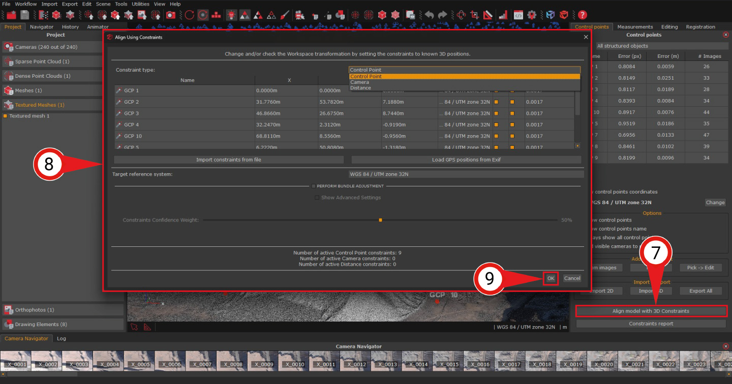
As for 3D constraints, just click on “Align model with 3D constraints” (7), and the “Align using constraints” (8) window will appear, thus allowing you to choose the constraints to be used by the bundle adjustment (ground control points, control distances, or camera coordinates). Click the “Ok” (9) button once ready.
The minimum number of control points set as constraints to run the bundle adjustment is 3. Nonetheless, using a greater number of control points is recommended, as this helps improve the robustness of the bundle adjustment and enhances the overall accuracy of the results, especially in complex or high-precision scenarios.
You should increase the bundle adjustment slider value only when you increase the number of control points defined in the workspace accordingly. Otherwise, you may experience high deviations in areas of the 3D model unaffected by the constraints.
It’s also advisable to set some control points as constraints – “CS” column in the “Align using constraints” (8) window – and others as “checkpoints” – “CK” column in the “Align using constraints” (8) window – so that the metric error can be monitored across the 3D model.
To understand the difference between constraints and checkpoints in Zephyr, please refer to our FAQ section.