Import Constraints
These functions are not available in 3DF Zephyr Lite and 3DF Zephyr Free.
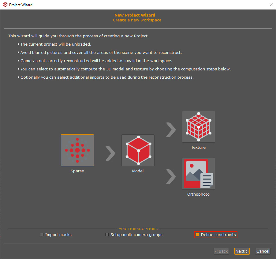
As part of the workflow for creating a new project, constraints can be set by importing known 3D positions from external control points and geographic positions from images. To do this, the "Define constraints" check-box should be activated on the first page of the New Project Wizard.
Note: camera position constraints with RTK coordinates will be recognized automatically.

The Import Constraint page will follow the Camera calibration page.
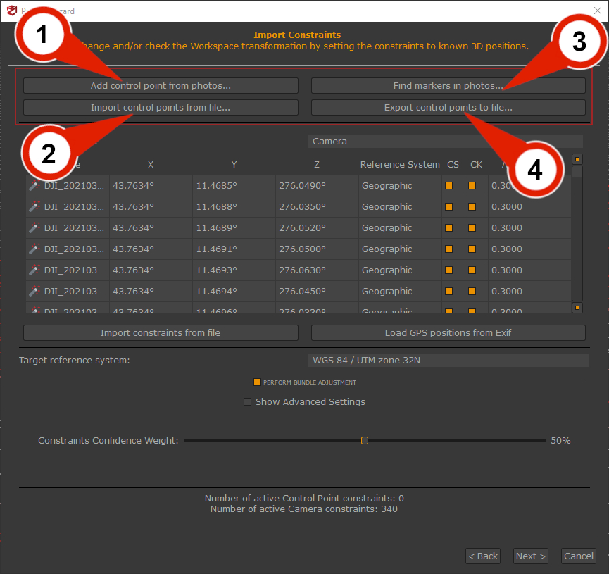
In the page's upper section, it's possible to open different tools for control point management.

Add control points from photo (1):
This tool allows the placement editing of 2D image coordinates, picking control points directly from the photos.
For the scaling process, you must place each control point on at least three pictures. It is also advisable to pick the control point on as many pictures as possible if you plan to leverage control points to adjust the camera positions using the Bundle Adjustment optimization.
The use of this feature is suitable for dealing with small/medium number images and in special cases where you want to improve image orientation by providing more data to the 3DF Zephyr SFM algorithm.
Import control points from file (2):
It opens the import control point tool for importing 2D image coordinates from text or csv files.
This feature is advisable when you have already created project 1 with oriented images associated with spatial coordinates and want to use them in project 2 to improve the orientation of cameras in special cases. If you are also dealing with huge datasets and/or large numbers of control points, then you can import GCPs at once rather than scrolling the whole set of images again; it may be way more time-saving.
Find markers in photos (3):
It opens the Detect marker tool for finding automatically markers placed in the scene.
Export control points to file (4):
This function allows to export 2D image coordinates associated with Ground Control Points (GCP) to a text or CSV file, creating a *ControlPoints2D.txt file. Each line defines a GCP as a 2D image coordinate:
"GCP1" "IMG_3319.jpg" 4.33473658e+03 2.24061730e+03
"GCP1" "IMG_3320.jpg" 3.30352087e+03 2.42468881e+03
"GCP2" "IMG_3319.jpg" 3.01642756e+03 3.16114630e+03
"GCP2" "IMG_3320.jpg" 1.68567672e+03 2.14786953e+03
The middle section it features the constraint tab.

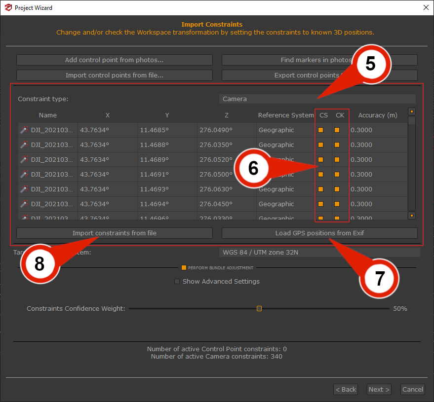
The Constraint type filter (5) allows to change the view to
- Camera: this option allows viewing the GPS coordinates of each image.
- Control point: this option will allow the display of the imported constraints from an external source.
Pressing "CTRL+A" will allow selecting all the tab rows, and "Right-click" with the cursor will allow you to change Reference system and Accuracy for each camera or control point.
Constraints and Check Points column (6)
Each control point can be set as Checkpoint (to measure the residuals), Constraint (used in the bundle adjustment), or both by using the check-boxes on the left of each point. It's always a good idea to include some checkpoints that are not set as constraints.
- Constraints (CS) are those points you are most confident of in terms of accuracy level, and 3DF Zephyr relies on them to drive the scaling process.
- Checkpoints (CK) are references that the software only considers while scaling to monitor the error value.
Load GPS position from Exif (7)
This button import camera positions by loading them from Exif information and using them as constraints.
A common scenario is when loading information from images taken by drones or UAV systems that record the GPS coordinates of the shots in Exif data.
Import constraints from a file (8)
this function allows directly set constraints from a text or .csv file via the "Import constraints from file" button; the imported coordinates and the GCPs you have added to the project must have the same name/label.
Coordinates should be defined using the following syntax:
"Control_Point_1" 8.18880729e-01 -5.14516149e-01 4.54143586e-01
"Control_Point _2" -5.64690812e-01 -5.65085273e-01 1.09244112e+00
Note: control points coordinates can be selected and imported after creating a sparse point cloud from the "Align model with 3D constraints" menu.
The lower wizard's section displays the Target reference system and the Bundle Adjustment check-box.
The Reference System can be changed by clicking on it and choosing the Select reference system option from the drop-down menu.
The Projection Coordinates System window will be open:
It's possible to select the new coordinate reference system from the 3DF Zephyr database, or import a new one from an external source by clicking the "Import" button and clicking "OK".
Optionally, a Geoid Gravity Model can also be loaded in relation to the Coordinate Reference System.
Bundle Adjustment check-box
It's possible to enable/disable the "Perform Bundle Adjustment" option to optimize the camera positions, and minimizing the reprojection error of the control points you have added to the project. The slider will allow setting the global confidence weight for the control points used as constraints.
