Tools - Registration
These functions are not available in 3DF Zephyr Lite and 3DF Zephyr Free.
The Registration menu allows the user to handle point clouds registration. From this menu you can access to the:
Point cloud registration (ICP)
The Iterative Closest Point (ICP) function is an algorithm that minimizes the geometric difference between two point clouds, and generates a point cloud difference report as output.
This tool can be used to align a laser scanned point cloud with a photogrammetric point cloud, accounting for translation, rotation, and scale. Once aligned, the laser scan can be further processed, for example, structured and colored using the photogrammetric point cloud.
Note: If the point clouds are still too far apart, the Gizmo  tool, allows to manually bring them closer together before proceeding with another ICP iteration.
Multi view point cloud bundle adjustment (Multi ICP)
Use this tool is advised when you dealing with many point clouds that are already in the correct scale system, for example multiple scans from a laser scanner device. This function does not apply any scale factor.
Please remember that:
- The objects must be close to each other
- You can use this tool to register multiple unstructured objects and structured ones
- The adjustment and the minimization will be performed in a global way
- If you need to register point sets with different scales, it is advisable to use the two view ICP dialog and enable scaling.
The fist wizard page will ask which objects will interact:

The next page will allow the selection of the reference object. Then, you will be able to define the object pairings:
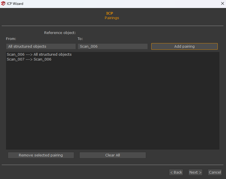
In most cases, pairings should not be changed as they should be automatically selected so no other interaction from the user is requested. Finally, you can define the stop conditions before you are shown a recap page where you can start the actual computation.
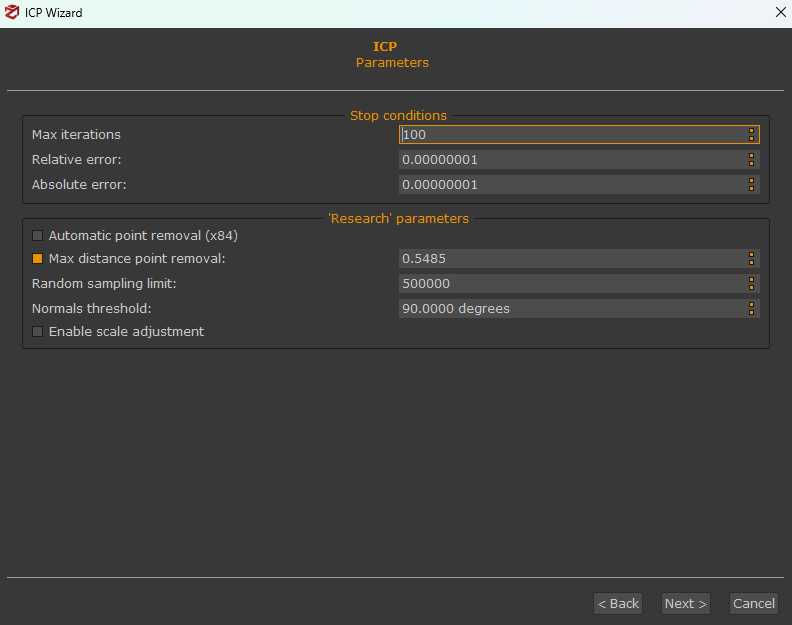
A summary of the set parameters will be displayed, and then procedure can be started by pressing the Start button."
Max distance point removal: when two or more point clouds are registered using the ICP algorithm, the corresponding points are calculated at each iteration by the algorithm itself.
Since it often occurs that point clouds depict different areas of a certain object/scene, a procedure to remove too far corresponding points needs to be applied. Indeed, the registration process would lead to a wrong result without that removal step.
The removal threshold can be calculated:
- automatically (X84 statistical analysis between point distances);
- manually (user is requested to set a metric value);
Point cloud comparison
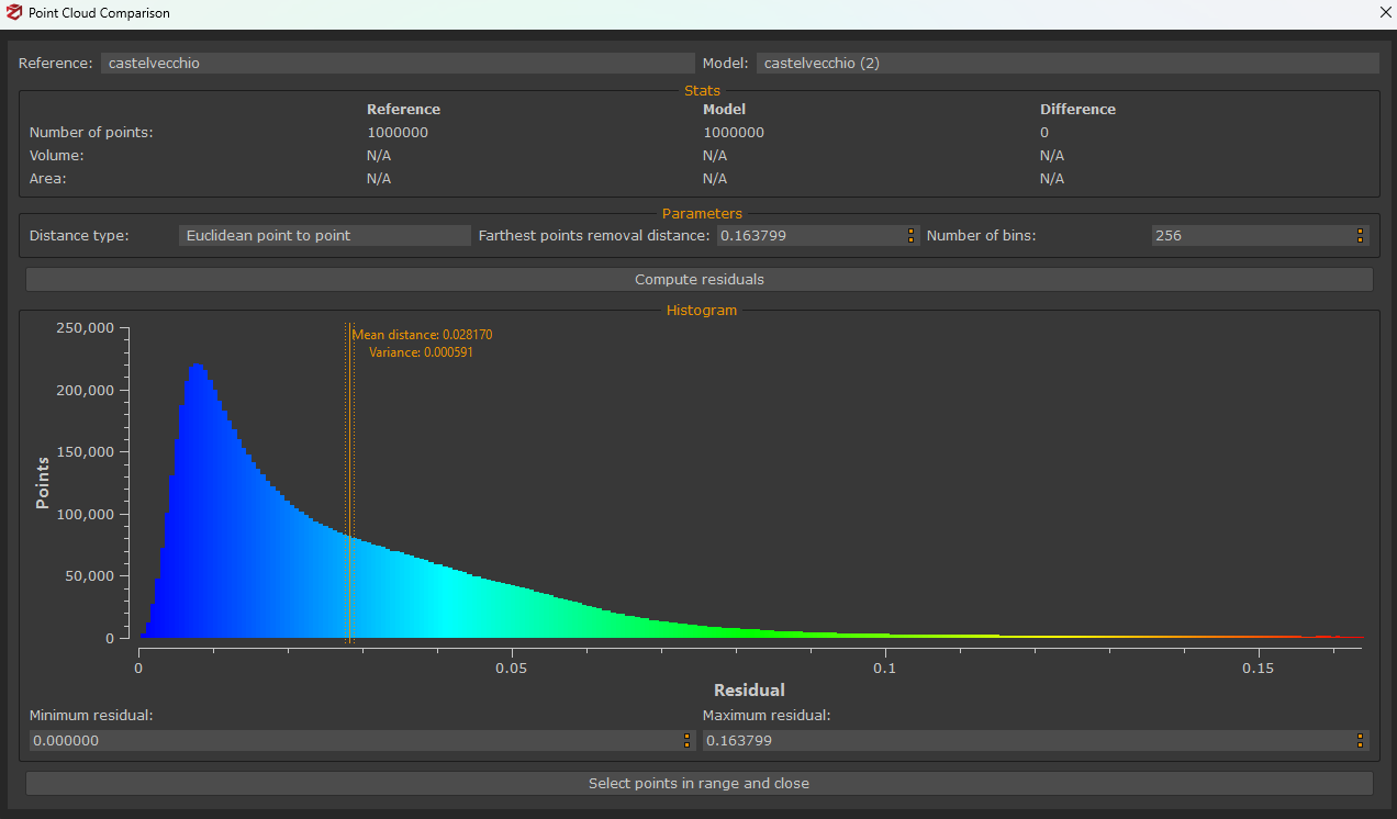
This function allows computation of a comparison between two selected point clouds. A chart is then plotted that graphically explains the residuals as a histogram. You can notice the errors recap on the bottom of the window (mean error and variance). Users should run this tool after the two clouds have been aligned to each other. Cloud comparison parameter settings are as follows:
- Distance type: indicates the distance to be calculated and users can choose either "point to point" or "plane to point" distance;
- Farthest points removal distance: represents the highest value during the histogram computation;
- Number of Bins: defines the histogram amount of columns;
As for the residuals computation process:
- The first step computes the closest point of the model for every point of the target;
- If a distance between a couple of points is greater than the maximum distance value, that distance won't be considered into the computation;
It is also possible to select parts of the histogram to highlight only a certain number of points of the "model" point cloud directly in the 3D room.
In the 'Point to point' comparison the histogram is built by considering the closest point A for each point B. All the spatial distances are from A to B are used to build the histogram and color the point cloud accordingly. The 'Plane' metric is a bit different. In this case a plane is fitted considering B and its neighbors. The distance is then calculated from A to the fitted plane. The latter is useful with buildings and walls.
Match objects center
This tool is useful when a photogrammetric dense point cloud has already been created and a laser scan is then imported into the project. In some cases, the scan may have been acquired in a different coordinate reference system than the photogrammetric dense point cloud, causing it to appear displaced or entirely invisible in Zephyr's 3D workspace.
The Match Objects Center tool resolves this by repositioning the imported scan so that its center aligns with that of an existing structured object, typically the photogrammetric dense point cloud, making both datasets visible and spatially close to one another.
Control points registration
Ground Control Points (GCPs) can be used to pre-align a photogrammetric point cloud with a laser scan point cloud.
After importing the laser scan, the workflow requires placing at least three control points on the first point cloud, then identifying and applying the same control points on the second.
Depending on the workflow, you may choose to move either the photogrammetric or the laser scan point cloud, the procedure is the same in both cases.
When choosing control point locations, keep the following guidelines in mind:
- Use well-defined features such as edges or corners, which can be easily and consistently identified across both point clouds.
- Distribute points across all three axes (X, Y, Z) to ensure a robust and accurate alignment.
Note: control points are grouped by Object (photogrammetric point cloud/laser scan) in the “Control points” panel.

For the photogrammetric dense point cloud, adding GCPs with the "From Images" tool is recommended for greater accuracy.

When working with an unstructured laser scan, GCPs can be picked directly in the 3D view using the "Pick" command.
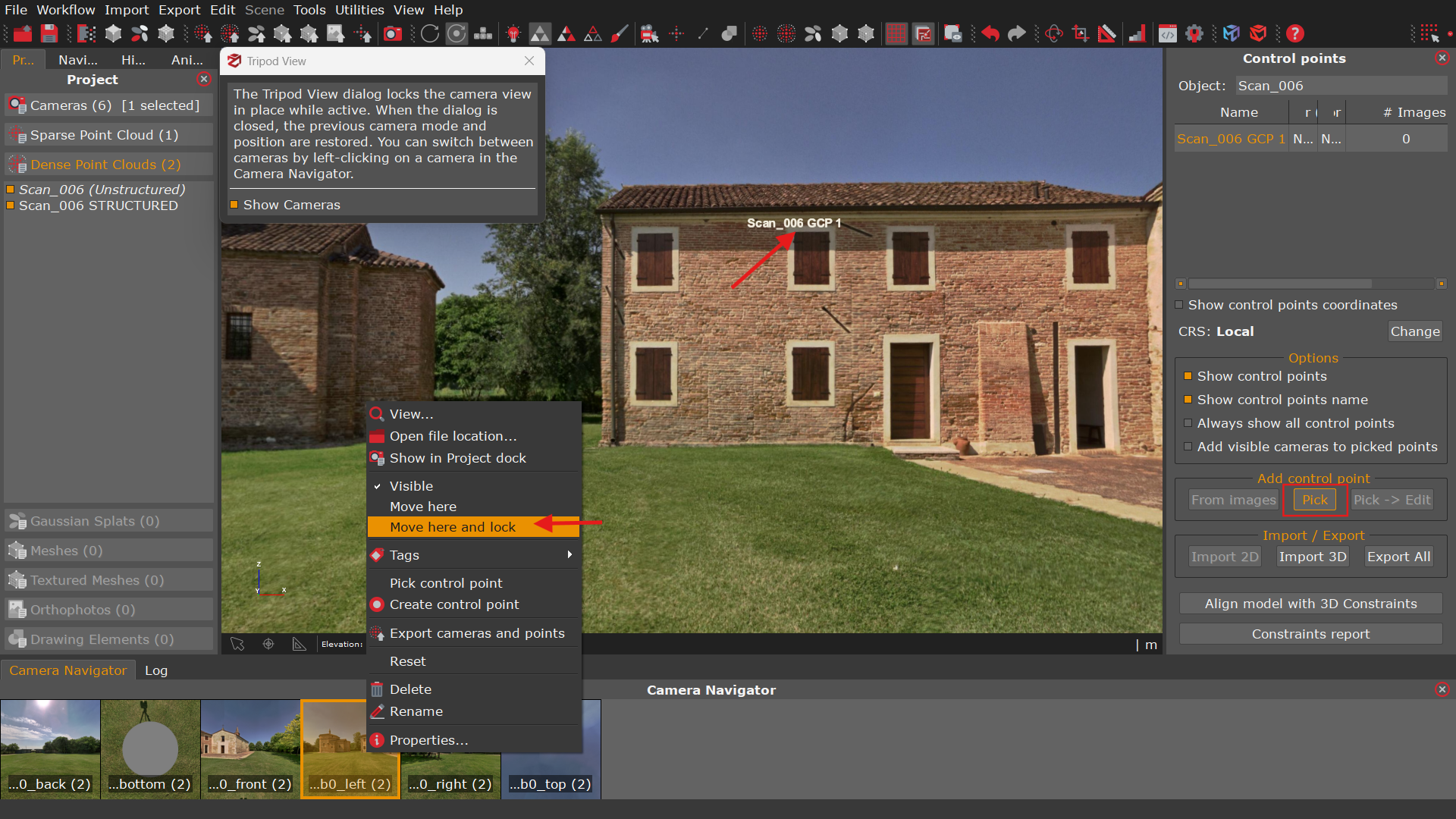
Use the Tripod View to define Control Points
If bubble view data is available in the imported scans, it is possible to structure the scans (see the Structuring Laser Scan section.) first and then use the bubble view to place Ground Control Points (GCPs) more accurately.
In the Camera Navigator, select the desired image, then press Right-click to display the "Move Here and Lock" option.
The Tripod View dialog locks the camera view in place while it is active. When the dialog is closed, the previous camera mode and position are restored. To switch between cameras, left-click on the desired camera in the Camera Navigator.
In the Control Point panel, GCPs can be picked directly on the Tripod View by enabling the "Pick" button.
When all the control points have been placed, simply select Tools > Registration > Control points registration from the menu.

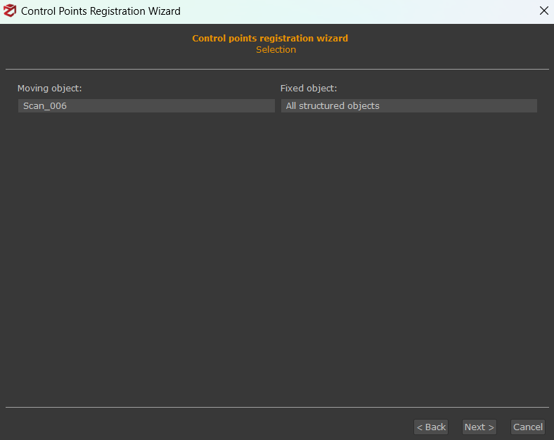
Select which object will move and which one will stay in its position.
Use the “Add Constraint” button to select the pairings, according to your naming convention that you used earlier. At least three constraints are required.
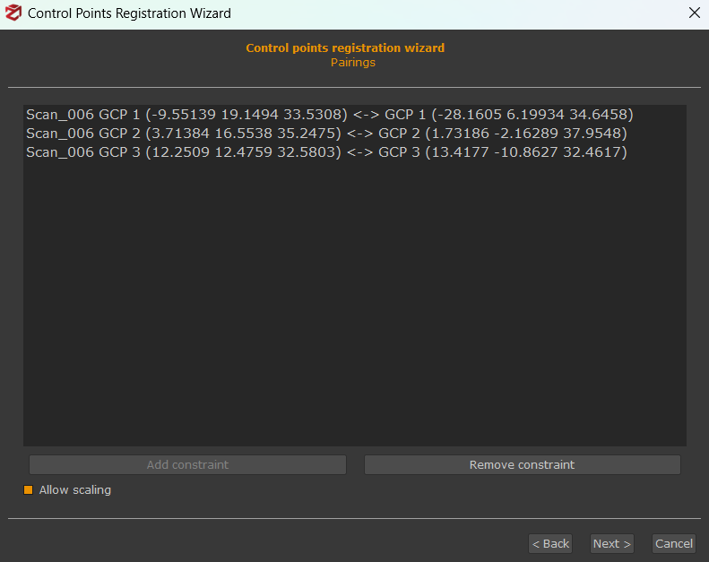
When ready, click “Next” and the summary will appear. Click “Apply” to continue.
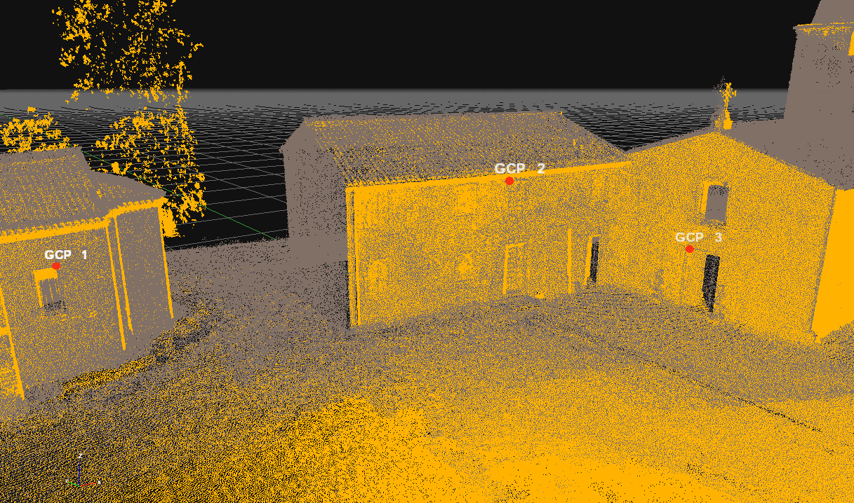
At this point, the point clouds have been aligned correctly. An additional ICP step is advised at this point to minimize errors.
Structuring laser scans:
Once the registration is completed, simply select the desired dense point cloud from the “Project” Tab, right click it and then click “Make structured”. Select the options accordingly to your needs, as shown below:
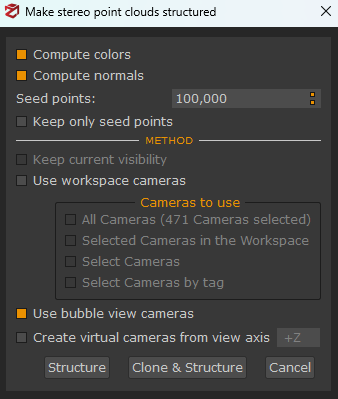
After the structuring, now you are ready for the mesh generation. Please remember to select the correct amount of seed points from this dialog according to the level of detail you want to obtain in your final mesh.